



































Outdoor LED Display Upgrade Guide: Smart Fault Diagnosis & Auto-Dimming
Outdoor LED Display Upgrade Guide: How Smart LED Modules Enable Fault Warning and Automatic Dimming
Outdoor LED displays are widely used in Digital Out-of-Home advertising, transportation hubs, commercial buildings, stadiums, and smart city infrastructure. As these displays become larger and more distributed, traditional maintenance methods can no longer meet the demand for high uptime, lower energy consumption, and faster fault response.
Common operational problems include dead pixels, module blackouts, abnormal temperatures, unstable power supplies, excessive nighttime brightness, and delayed maintenance. If these issues are not detected quickly, they can reduce advertising performance, increase operating costs, and damage the display operator’s reputation.
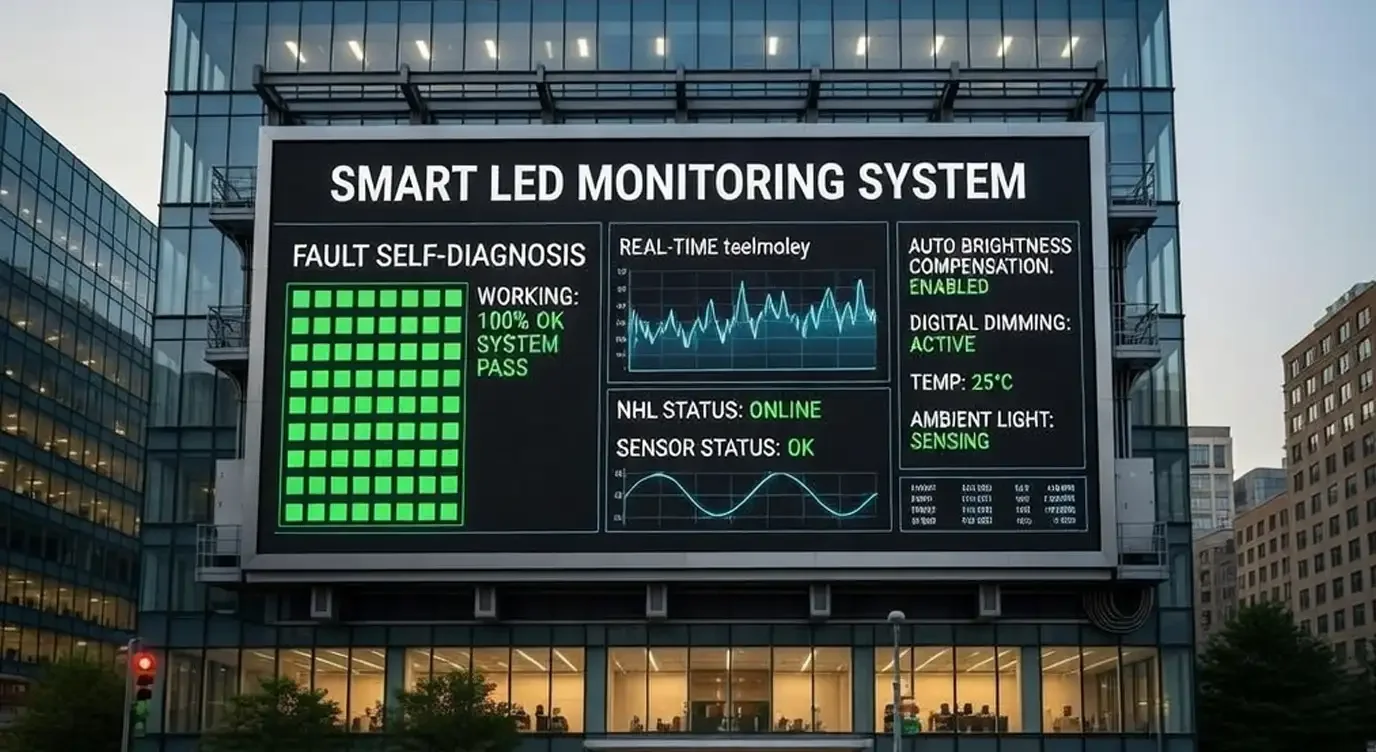
A Smart LED Module addresses these challenges by integrating local processing, environmental sensing, fault detection, and communication capabilities directly into the LED module. Instead of operating as a passive display component, each module becomes part of an intelligent monitoring network.
This guide explains how smart inspection modules can modernize outdoor LED display maintenance, improve fault diagnosis, support automatic brightness adjustment, and enable centralized remote monitoring.
What Is a Smart LED Module?
A Smart LED Module is an LED display module equipped with embedded monitoring and control capabilities. It can collect operating data, identify abnormal conditions, and transmit status information to a local controller or cloud-based management platform.
Depending on the system design, a smart module may include:
A Microcontroller Unit, or MCU
Ambient light, temperature, and humidity sensors
Voltage and current monitoring circuits
LED driver IC status detection
Module identification and positioning
RS485, PLC, CAN, Ethernet, or IoT communication interfaces
Local data processing and warning functions
Brightness and thermal control capabilities
The purpose of a smart module is not simply to display content. It also helps operators understand whether the module is functioning correctly, where a fault has occurred, and when maintenance may be required.
In simple terms, a Smart LED Module transforms an outdoor LED screen from a passive display into a self-monitoring and remotely manageable digital asset.
Why Traditional Outdoor LED Display Maintenance Is Inefficient
Conventional LED displays generally depend on manual inspections, visual observations, and fault reports from advertisers or site operators. This reactive maintenance model creates several operational limitations.
1. Faults Are Often Discovered Too Late
Dead pixels, color inconsistencies, overheating, communication interruptions, and partial blackouts may remain unnoticed until someone reports them.
For roadside billboards or geographically distributed display networks, a fault may continue for hours or days before the maintenance team receives accurate information.
2. Manual Inspections Increase O&M Costs
Inspecting large outdoor screens may require technicians, lifting equipment, road access coordination, and temporary screen shutdowns.
If technicians do not know the precise fault location or cause before arriving, they may also need to make multiple site visits or carry unnecessary replacement parts.
3. Fixed Brightness Wastes Energy
Outdoor LED displays must remain visible under strong daylight. However, using the same brightness level at night can waste electricity and create uncomfortable glare.
A fixed-brightness system may also make it more difficult to comply with local rules governing nighttime luminance and light pollution.
4. Maintenance Decisions Lack Data
Traditional systems provide limited historical information about voltage fluctuations, thermal conditions, humidity exposure, or recurring module failures.
Without reliable operating data, maintenance teams are forced to respond to visible symptoms rather than addressing the underlying causes.
How Smart Inspection LED Modules Work
A smart inspection architecture adds sensing, processing, and communication functions to the LED display system.
The basic operating process includes four stages:
Data collection: Sensors and monitoring circuits collect temperature, voltage, current, brightness, humidity, and communication data.
Local analysis: The MCU compares the collected data with predefined operating thresholds.
Fault detection: Abnormal conditions, such as overheating, unstable voltage, communication loss, or driver failure, trigger an event.
Remote reporting: The module sends the event and its location to an LED screen remote monitoring platform.
This architecture enables maintenance teams to monitor the condition of the display without relying entirely on physical inspections.
Real-Time LED Display Fault Diagnosis
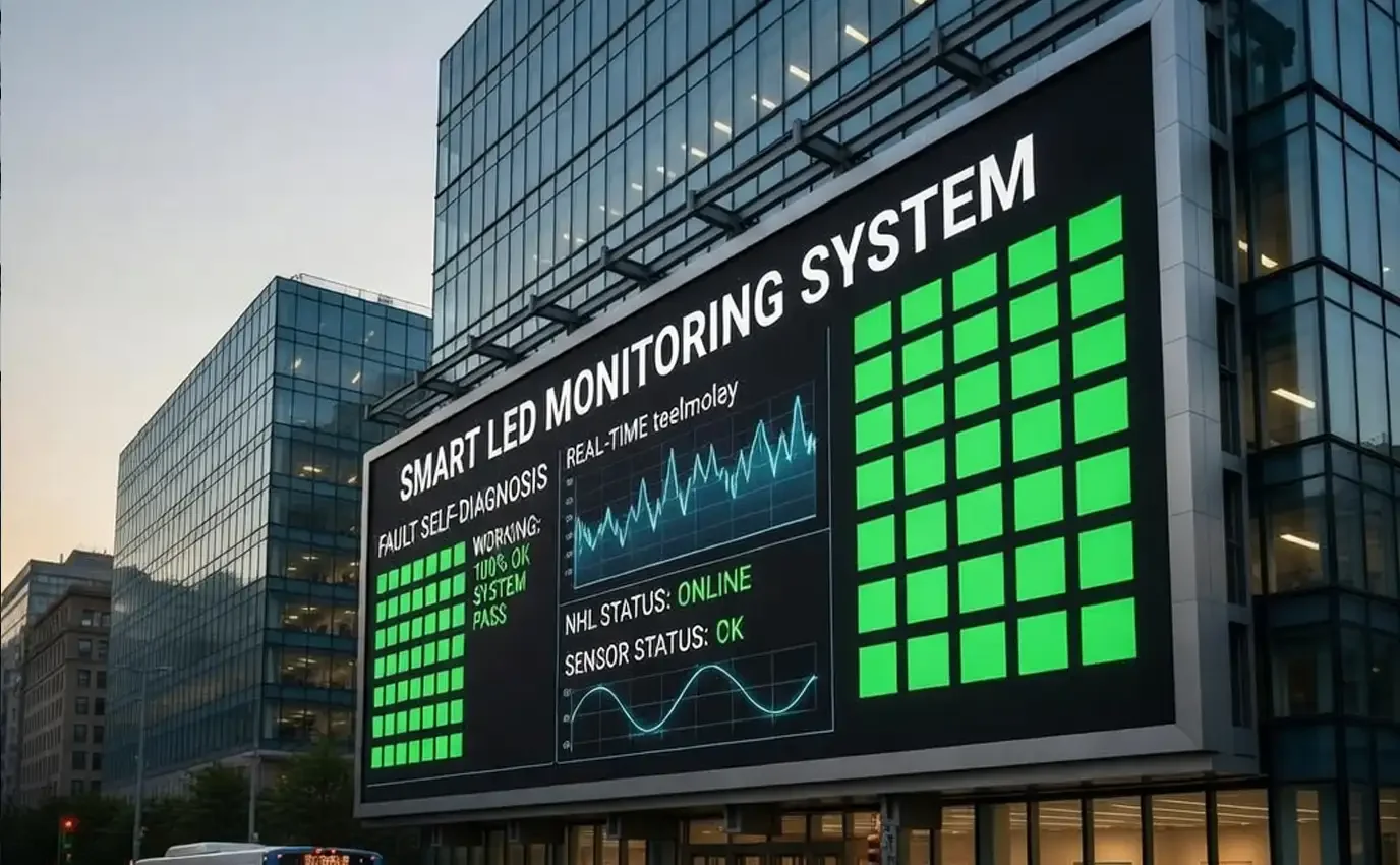
One of the most important benefits of a Smart LED Module is its ability to support continuous LED display fault diagnosis.
Instead of waiting for a visible failure, the system can identify early warning signals and notify the maintenance team before the issue becomes more serious.
Component-Level Condition Monitoring
A smart inspection system may monitor:
Module input voltage
Current consumption
PCB and cabinet temperature
LED driver IC condition
Power supply stability
Data transmission quality
Communication interruptions
Fan or cooling-system operation
Ambient humidity
Abnormal brightness output
The specific diagnostic capability depends on the module design, sensor configuration, and control system.
Automated Fault Warnings
When a monitored value exceeds its normal operating range, the system can automatically generate a warning.
Alerts may be delivered through:
Cloud management dashboards
Mobile applications
Email notifications
SMS messages
Local control-room software
Third-party maintenance platforms
API integrations
Each warning can include the screen ID, cabinet number, module location, fault type, event time, and current operating data.
Precise Fault Localization
Traditional maintenance often identifies only that a screen has a problem. A smart monitoring system can help identify exactly where the issue is located.
Fault localization may be organized by:
Display site
Screen section
Receiving card
Cabinet
Power supply
LED module
Driver circuit
This information allows technicians to prepare the correct tools and replacement components before traveling to the site.
As a result, operators may reduce troubleshooting time, avoid unnecessary inspections, and improve Mean Time to Repair, or MTTR.
Automatic LED Dimming Based on Ambient Light
Outdoor LED displays operate under changing light conditions. A display may need high brightness during direct sunlight but only a fraction of that output after sunset.
An Automatic LED Dimming System uses ambient light measurements and predefined dimming logic to adjust screen brightness dynamically.
How Automatic Brightness Adjustment Works
The system typically follows this process:
An ambient light sensor measures environmental illuminance in lux.
The controller filters temporary changes caused by headlights, shadows, or weather.
The measured data is matched with a configured brightness curve.
The MCU or display controller adjusts LED output through PWM or compatible driver control.
The monitoring platform records brightness changes and sensor status.
This allows the display to maintain sufficient visibility without operating at maximum brightness at all times.
Daytime Display Performance
During bright daylight, the control system can increase LED output to maintain image visibility and contrast.
The system may also consider:
Screen orientation
Direct sunlight exposure
Seasonal changes
Weather conditions
Installation environment
Content characteristics
Nighttime Brightness Control
After sunset, the system reduces brightness gradually rather than switching abruptly between fixed settings.
This can help:
Reduce unnecessary electricity consumption
Minimize glare for drivers and pedestrians
Improve nighttime viewing comfort
Lower thermal stress on LEDs and power supplies
Support local light pollution requirements
Maintaining Grayscale and Color Quality
A professional automatic dimming system must do more than reduce current output. It should preserve grayscale performance, color consistency, refresh rate, and low-brightness image quality.
High-precision PWM control and calibrated brightness curves can help prevent:
Grayscale loss
Color distortion
Visible flicker
Uneven module brightness
Sudden luminance changes
The objective is to reduce brightness while maintaining stable visual performance.
LED Screen Remote Monitoring for Distributed Display Networks
For operators managing multiple displays, local fault detection is only part of the solution. The collected information must also be available through a centralized LED Screen Remote Monitoring platform.
A remote monitoring system gives operators real-time visibility into the condition of displays across different locations.
Information Available Through a Remote Monitoring Dashboard
Depending on system configuration, the dashboard may display:
Online or offline status
Module and cabinet condition
Screen brightness
Ambient light levels
Internal temperature
Humidity data
Voltage and current readings
Power supply status
Communication quality
Fault history
Maintenance records
Energy consumption trends
Centralized Multi-Site Management
A cloud-based platform can organize displays by city, customer, project, site, or maintenance region.
This is especially valuable for:
DOOH advertising networks
Smart city projects
Highway and roadside signage
Transportation information displays
Shopping mall media networks
Stadium displays
Municipal information systems
Maintenance teams can prioritize faults by severity instead of treating every alert as an emergency.
Integration with Existing Platforms
Smart LED modules can also be connected to external systems through APIs, gateways, or standard industrial communication interfaces.
Potential integrations include:
Content Management Systems
Building Management Systems
Smart city IoT platforms
Energy management platforms
Maintenance ticketing systems
Enterprise asset management software
This makes the LED display part of a broader connected infrastructure rather than an isolated visual device.
Predictive Maintenance vs. Reactive Maintenance
Traditional LED display maintenance is reactive: technicians respond after a visible failure occurs.
Smart inspection technology supports a more predictive approach by identifying operating trends before they lead to complete failure.
For example:
A gradual temperature increase may indicate reduced ventilation.
Repeated voltage fluctuations may suggest power supply instability.
Rising current consumption may reveal component degradation.
Intermittent communication loss may indicate a cable or connector issue.
Increasing humidity may signal a sealing or waterproofing problem.
By reviewing historical data, operators can schedule maintenance during planned service windows instead of waiting for an emergency.
Comparison of Maintenance Models
| Maintenance Area | Traditional LED Display | Smart LED Module System |
|---|---|---|
| Fault discovery | Manual inspection or customer report | Automated monitoring and alerts |
| Fault location | On-site troubleshooting | Remote cabinet or module localization |
| Brightness control | Fixed or scheduled settings | Sensor-based dynamic adjustment |
| Maintenance strategy | Reactive | Preventive or predictive |
| Operating data | Limited | Real-time and historical data |
| Multi-site management | Separate local systems | Centralized monitoring platform |
| Energy optimization | Basic | Automated and data-driven |
Business Benefits of Upgrading Outdoor LED Displays
The value of a smart inspection system extends beyond technical monitoring. It can improve the financial and operational performance of the entire display network.
1. Lower Maintenance Costs
Remote diagnosis reduces the need for routine physical inspections. When a site visit is necessary, technicians can arrive with information about the probable fault location and required replacement parts.
Potential savings may come from:
Fewer inspection visits
Shorter troubleshooting time
Better technician scheduling
Reduced lifting-equipment use
Fewer repeat service calls
More efficient spare-parts management
Actual cost reductions depend on network size, display location, maintenance processes, and the level of system integration.
2. Higher Display Uptime
Early fault warnings allow operators to respond before a minor abnormality causes a large screen section to fail.
Higher uptime supports:
Stable advertising playback
Better client service
Fewer compensation claims
Improved contract performance
Stronger operator reputation
3. Reduced Energy Consumption
Automatic brightness adjustment prevents the screen from operating at excessive brightness when environmental conditions do not require it.
The amount of energy saved depends on factors such as:
Daily operating hours
Daytime and nighttime brightness settings
Local weather
Display size
LED efficiency
Content type
Dimming strategy
In suitable applications, dynamic brightness control can generate meaningful energy savings compared with continuous high-brightness operation.
4. Longer Component Service Life
Heat is a major factor in the aging of LEDs, driver ICs, power supplies, and other electronic components.
Thermal monitoring and controlled brightness can reduce unnecessary operating stress, helping to slow:
LED lumen depreciation
Color inconsistency
Power supply degradation
Driver IC failure
PCB and connector aging
5. Better Regulatory Management
A programmable automatic dimming system helps operators configure brightness according to local requirements and different time periods.
The system can also create operating records, which may help demonstrate that brightness policies were implemented consistently.
Because regulations vary by location, operators should always confirm the applicable municipal, transportation, zoning, and environmental requirements.
Key Features to Consider When Selecting a Smart LED Module
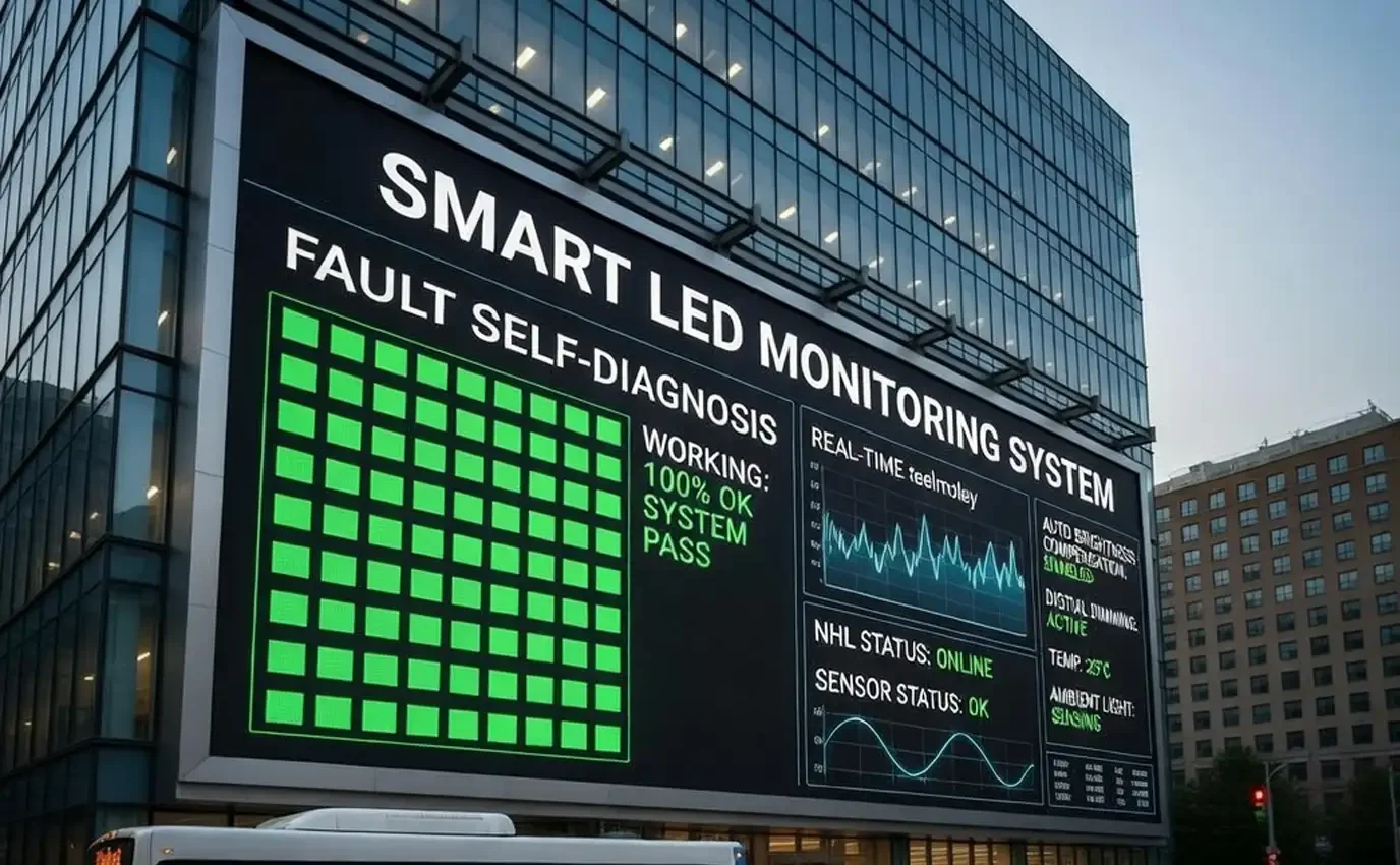
Not all smart inspection solutions provide the same level of functionality. Buyers should evaluate both the hardware and the management platform.
Hardware Monitoring
Confirm which parameters can be measured:
Temperature
Humidity
Voltage
Current
Ambient light
Driver status
Power supply status
Communication quality
Diagnostic Precision
Determine whether the system identifies faults at the screen, cabinet, module, or component level.
Greater diagnostic precision can reduce troubleshooting time, but it may also require more advanced hardware and software integration.
Communication Compatibility
Check compatibility with the project’s existing infrastructure, including:
RS485
PLC
CAN
Ethernet
4G or 5G gateways
Wi-Fi
LoRa or other IoT networks
Custom communication protocols
Dimming Performance
Evaluate whether the system provides:
Smooth brightness transitions
Adjustable dimming curves
Minimum and maximum brightness limits
Sensor calibration
Manual override
Scheduled control
Low-brightness grayscale optimization
Multi-sensor redundancy
Software and Cloud Management
The monitoring platform should provide:
Real-time status visualization
Fault severity classification
Historical data
Custom alert thresholds
User permission management
Maintenance records
Multi-site organization
API access
Exportable reports
Environmental Reliability
Outdoor modules must be designed for demanding environments. Buyers should review the system’s operating temperature, waterproofing, corrosion resistance, electromagnetic compatibility, and long-term sensor stability.
How to Upgrade an Existing Outdoor LED Display
The upgrade process depends on whether the current display hardware supports smart monitoring functions.
Step 1: Audit the Existing System
Document the current:
LED module specifications
Cabinet architecture
Receiving cards
Control system
Power supplies
Communication wiring
Brightness control method
Maintenance workflow
Step 2: Define Monitoring Requirements
Identify the most important operational problems.
For example:
Are power supply failures the main issue?
Is nighttime brightness difficult to control?
Are displays located far from maintenance teams?
Is module-level fault localization required?
Does the platform need to manage multiple cities?
Step 3: Evaluate Compatibility
Determine whether the upgrade requires:
Full module replacement
Additional sensor boards
A new receiving-card system
Communication gateways
Cloud software integration
Power or data cable modifications
Step 4: Run a Pilot Project
Before upgrading an entire network, test the system on one display or a limited number of cabinets.
The pilot should verify:
Data accuracy
Fault detection performance
Alert reliability
Dimming smoothness
Platform compatibility
Network stability
Maintenance response improvements
Step 5: Establish Alert and Maintenance Rules
Not every abnormal reading requires an immediate site visit. Configure alert levels such as:
Information
Warning
Critical
Emergency
Link each level to a defined maintenance procedure.
Step 6: Review Performance Data
After deployment, compare the new system with previous maintenance records.
Useful performance indicators include:
Display uptime
Number of site visits
Mean Time to Detect
Mean Time to Repair
Energy consumption
Fault recurrence rate
Maintenance cost per display
Frequently Asked Questions
-
 Outdoor LED Screen | Weatherproof P2.9-P10.4 Display
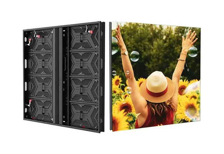
REISSOPTO outdoor LED screen (P2.9–P10.4) delivers up to 6500 nits brightness, IP65 waterproof, front/rear maintenance f...
-
 Outdoor 3D LED Display | Glasses-Free 3D Advertising Screen
Outdoor 3D LED display delivers glasses-free naked-eye 3D visuals, up to 10,000 nits brightness, IP66 protection and fro...
-
 P4.81 Outdoor LED Display - Outdoor High Resolution Display
P4.81 outdoor LED display with IP66 waterproof design, up to 6500 nits brightness, 500×1000mm cabinet and front/rear ser...
-
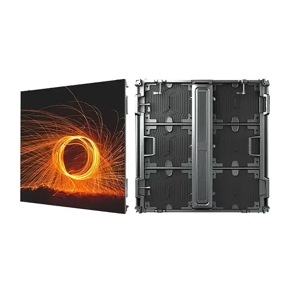 P8 Outdoor LED Display – IP68 Waterproof, 10,000-Nit High-Brightness LED Advertising Billboard
P8 outdoor LED screen delivers high-visibility outdoor advertising with strong brightness, weatherproof design, and stab...